Coastal Hydrodynamics And Transport Processes
The hydrodynamic conditions or processes, that come about from waves transforming over a coastal profile and generating wave set up and longshore currents, will result in movement and transport of the sediments (e.g. sand) present in the profile. This is referred to as littoral transport processes and is the main subject of this article. However, transport of fine sediments will also be discussed, but only very briefly.
Contents
Sediment transport, General
The sediment on the seabed is transported when it is exposed to large enough forces, or shear stresses, by the water movements. These movements can be caused by the current or by the wave orbital velocities or a combination of both, the latter being the most important situation. The relevant parameters for the description of the sediment transport along a shoreline or in a coastal area are therefore the following:
- The wave conditions at the site and the possible variations over the site plus the adjoining areas
- The current conditions as well as the variations of these over the area
- The water-level conditions, i.e. tide, storm surge and wave set-up
- The bathymetry (the depth variations) in the area
- The sediment characteristics over the area
- The sources and sinks of sediment, such as rivers, eroding coasts or tidal inlets
Littoral Transport
Littoral transport is the term used for the transport of non-cohesive sediments, i.e. mainly sand, in the littoral zone along a shoreline mainly due to the action of breaking waves. The littoral transport is also called the longshore transport or the littoral drift.
Description
Littoral transport is often described under the assumption that the shoreline is nearly straight with nearly parallel depth contours. This assumption is very often valid, especially if the sections of the shore are not too long and if a gradual transition between such sections is assumed. Under these circumstances, the littoral transport can briefly be described as follows.
When waves approach the shoreline obliquely, refraction tends to turn the wave fronts so that they are almost parallel to the shoreline. At the same time, when approaching the breaker-zone, they undergo shoaling, which means that they become steeper and higher. Finally, the waves break. During the breaking process, the associated turbulence causes some of the seabed sediments to be brought into suspension. These suspended sediments, plus some of the sediments on the seabed, are then carried along the shoreline by the longshore current, which has its maximum near the breaker-line. The two transport modes are referred to as suspended transport and bed load, respectively. The sum of these is the littoral drift.
Distribution of the Littoral Transport
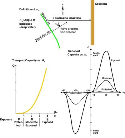
The magnitude of the littoral transport or drift, Q, depends on parameters, the most important of which are:
- Wave height. The littoral drift is proportional to the wave height to the power of approximately 3.
- Grain size. The littoral drift is inversely proportional to the grain size to the power of approximately 3.
- Wave incidence angle. The littoral drift is approximately proportional to sin2.5(2α), where α is the wave incidence angle.
- Variation in littoral transport with wave exposure and wave incidence angle.
It can be seen that the littoral drift varies strongly with several parameters. It is therefore crucial to have exact data when making littoral drift calculations. It is an important point that the littoral drift over the coastal profile depends not only on the hydrodynamics but also very much on the variation of the sediment characteristics over the profile. Hence, the sediment distribution along the coastal profile should be taken into account whenever possible.
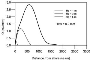
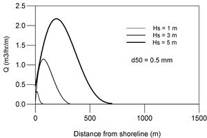
- Distribution of the littoral transport over a coastal profile for grain sizes D50 = 0.2 mm and 0.5 mm and for the wave heights HS = 1.0 m, 3.0 m and 5.0 m. Equilibrium profiles corresponding to the grain sizes have been used, Angle of incidence: α = 30o. Calculated by LITPACK.
It is noted that the transport covers different widths and depths of the coastal profile depending on the grain size as well as the wave height.
Littoral Drift Budgets
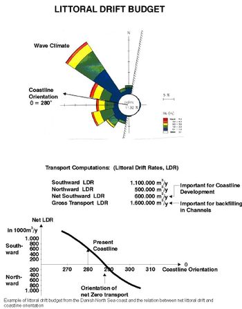
A littoral drift budget for a coastal profile is the sum of littoral transport contributions caused by all the possible combinations of wave heights and directions, as well as tide and storm surge.
Consider, for example, a coastline oriented north-south with the sea to the west. All wave components from south to west will yield northward littoral drift contributions, and all wave components from west to north will yield southward littoral drift contributions. The sum of the northward drift components is called the northward littoral drift, and similarly is the sum of the southward drift components referred to as the southward littoral drift. The difference between the northward and the southward littoral drifts is called the net littoral drift, which is associated with a net littoral drift direction. The sum of the northward and the southward drift rates is called the gross littoral drift, which has no direction.
Littoral drift budgets can be made for any period relevant for the site under study as long as there are sufficient data. An overview of the magnitude of littoral drift is provided in the following table as a function of the following parameters:
- The significant wave heights Hs
- The angle of incidence at 'deep water' α0 (20m has been used as 'deep water')
- A duration of 24 hours
- Beach sand with d50 = 0.25mm
- Calculations performed by LITPACK on the equilibrium profile corresponding to d50 = 0.25mm
| Q[m3/24hrs] | α0 | ||||||
|---|---|---|---|---|---|---|---|
| 5 | 15 | 30 | 45 | 60 | 75 | ||
| Hs | 1.0 | 50 | 100 | 300 | 350 | 300 | 150 |
| 2.0 | 400 | 1000 | 2,000 | 3,000 | 2,500 | 1,000 | |
| 3.0 | 1,500 | 4,000 | 10,000 | 15,000 | 10000 | 5,000 | |
| 4.0 | 4,000 | 10,000 | 30,000 | 40,000 | 35,000 | 15,000 | |
| 5.0 | 8,000 | 25,000 | 65,000 | 100,000 | 85,000 | 35,000 | |
- Note: D50=0.25mm, H and MWD at 20m water depth
- Image below right: Example of a littoral drift budget from the Danish North Sea Coast and the relation between net littoral drift and coastline orientation.
An important parameter in relation to the littoral drift conditions is the variation of the net transport with varying orientation of the coastline. If e.g. a groyne is constructed, this will initially block the transport resulting in net zero transport at this location. This means that the sand will accrete upstream of the groyne forming a coastline with the orientation, which gives zero transport. The efficiency of the groyne depends very much on the angle between the present orientation of the coastline and the orientation of net zero transport. If this angle is small, the groyne will be efficient, as it will be able to hold a long sand filet. If the angle is large, which is the case with a very oblique wave exposure, the groyne will only be able to hold a very short sand filet, which means that a groyne will not be an applicable type of coast protection in this case.
When discussing the littoral transport along a coastline in general, it is always the net littoral drift that is referred to unless otherwise specified. Gradients in the net littoral drift along a section of coast lead to coastline erosion or accretion. The gross littoral drift is important for backfilling of channels/trenches across the littoral drift zone, as all littoral drift situations lead to backfilling of the channel/trench.
The littoral drift also depends on the sea current, although to a much smaller extent than it depends on the longshore current. This means that the most important hydraulic parameter for the littoral transport is the wave conditions.
The water-level mainly determines where in the coastal profile the transport will take place, but the water-level only influences the magnitude of the littoral drift to a lesser extent. However, the tide may have significant influence on the transport conditions for macro-tidal environments. Positive or negative correlation between the waves and the water-level variations may be of importance for sedimentation patterns near large structures.
At many locations there is a considerable variation in the grain size depending on the distance from the coastline. Typically the sediments become finer with increasing distance from the coastline. This will, to some extent, blur the picture of the littoral drift given above.
The fine cohesive sediments, which may be present in the outer part of the profile, will be in suspension over the entire water column and will also tend to spread over the entire coastal profile during strong wave exposure. The transport which this gives rise to is normally not considered a part of the littoral drift, as this only takes the non-cohesive sediments into consideration. The transport of the cohesive sediments thus only plays an indirect role in the stability of the coastal profile. The existence of this transport of fine suspended sediments will, however, be of importance in relation to sedimentation in ports and in trenches.
The longshore transport is, as already mentioned, characterised by a combination of sediment moved along the seabed, the so-called bed load transport, and of sediment in suspension, the so-called ‘’suspended load’’. Even when the sand is in suspension it is still relatively close to the seabed because of the relatively high fall velocity of sand grains. This means that any change in the hydrodynamics or bathymetric conditions will "immediately" result in a corresponding change in the transport capacity and therefore also in the morphology. This results for instance in the typical accumulation of sand behind even a relatively short, detached, coastal breakwater, as the accumulation of sand reflects the “immediate” response on the attenuated transport capacity behind the breakwater. It is not possible to guide the sand between the coastal breakwater and the shoreline if the breakwater has a length of more than around 0.5 times the distance from the shoreline. If the length of the breakwater is more than approximately 0.8 times the distance from the shoreline so much sand will be trapped that the breakwater will be connected to land by a tombolo formation. This immediate morphological response to even small changes in the littoral transport is also the reason why many attempts to construct island-ports with zero impact on the shoreline have failed. Most of them have been connected to land by tombolo formations.
Onshore and Offshore Transport and Equilibrium Coastal Profile
Varying wave conditions result in varying onshore and offshore transports over the coastal profile. These transports are, to some extent, reversible and therefore non critical in terms of long term coastal stability. However, extreme storm surge and wave exposure result in coastal erosion.
Erosion and rebuilding sequence
When the coastal profile is exposed to non extreme waves and storm surge, the sediments near the shoreline will be transported offshore and typically be deposited in a bar resulting in an overall flattening of the slope of the shoreface. However, the inner part of the shoreface as well as the foreshore will become steeper in this process, and the shoreline will recede. During the following periods of smaller waves, swell and normal water-level conditions, the bar will travel very slowly towards the coastline again, practically rebuilding the original coastal profile.
During such a sequence of profile erosion and rebuilding, certain parts of the coastal profile may experience temporary erosion. This may not be recorded in profile surveys, because some rebuilding will already have taken place before it is possible to carry out surveys after the storm. It is important to take such temporary profile fluctuations into account when designing structures in the coastal zone. It is particularly important to have a sufficiently wide beach so that the temporary beach erosion will not cause erosion of the coast.
Coastal profile
This onshore and offshore transport is closely related to the form of the coastal profile. Several investigations have revealed that a coastal profile possesses an average, characteristic form, which is referred to as the theoretical equilibrium profile. The equilibrium profile has been defined asa statistical average profile, which maintains its form apart from small fluctuations, including seasonal fluctuations The depth d [meters] in the equilibrium profile increases exponentially with the distance x from the shoreline according to the equation[1]:
- d = A xm [x and d in meters]
where A is the dimensionless steepness parameter and m is a dimensionless exponent. Based on fitting to natural upper shoreface profiles, Dean, 1987[2] has suggested an average value of m = 0.67. However the value of m is subject to large variability dependent of the beach type expressed by the dimensionless fall velocity Ω = H0/ωsT where H0 is the deep water wave height, T is the wave period and ωs is the sediment fall velocity. The value of m varies typically between m ~ 0.4 for reflective beaches (Ω < 1.5) and m ~ 0.8 for dissipative beaches (Ω > 5.5).[3][4].
The steepness parameter A has empirically been related[5] to the sediment fall velocity ωs as follows:
- A = 0.067ωs0.44[ωs in cm s-1]
Values for A as a function of the mean grain size d50 is shown in the table below.
| d50 | 0.10 | 0.15 | 0.20 | 0.25 | 0.30 | 0.50 | 1.00 | 2.00 | 5.00 | 10.00 |
|---|---|---|---|---|---|---|---|---|---|---|
| A | 0.043 | 0.062 | 0.080 | 0.092 | 0.103 | 0.132 | 0.178 | 0.234 | 0.318 | 0.390 |
It is seen that the equilibrium profile does not depend on the wave height. The reason for this is that the water depth limits the wave height inside the breaker zone. However, the wave height decides the width of the littoral zone, within which the equilibrium shoreface concept is valid. Thus, the equilibrium profile is only valid for the littoral zone, i.e. out to the Closure Depth dl:
- d1 =2.28HS,12h/y - 68.5H2S,12h/y gT2s
The width of the littoral zone and the slope of the shoreface thus depend on the mean grain size as well as on the wave conditions.
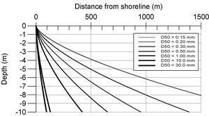
The equilibrium profile becomes increasingly steeper with increasing grain size. Typical equilibrium profiles for different grain size characteristics are presented in the following figure.
- Equilibrium profiles for grain sizes 0.15, 0.2, 0.3, 0.5, 1.0, 10 and 30 mm.
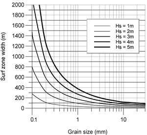
The width of the littoral zone as a function of the mean grain size and for different wave climates, represented by HS,12h/y, is presented in the following figure.
- Empirical width of littoral zone as a function of the mean grain size for various wave climates represented by HS,12h/y
These figures can be used in preliminary design considerations for artificial beaches and reclamation areas fronted by natural slopes.
It is evident from these correlations between grain size, equilibrium profile and wave conditions that it is very important in beach nourishment to use materials as coarse as or coarser than the native material. Otherwise the nourished sand will immediately be transported offshore in nature’s attempt to form the new and flatter equilibrium profile, which fits the finer sand.
In the real world there is often a sorting of the sediments in the active coastal profile; the mean grain size decreases with increasing distance from the shoreline. If this variation is introduced into the considerations concerning the equilibrium profile, a more accurate representation of the equilibrium profile at a specific site is obtained.
The concept of equilibrium profiles is a rather crude representation of the coastal profile conditions since it neither includes nor explains the occurrence of bar formations, etc. However, the concept of the equilibrium profile is a rather practical “tool” for the analysis of coastal conditions and, as already mentioned, for preliminary design considerations.
If the geological coastal profile at a location is flatter than the calculated equilibrium profile, the wave action in the profile will tend to form the equilibrium profile, which means that material will be moved towards the shore. However, at a certain location towards the shore, there is not sufficient wave energy to move the sand any further and a barrier with a corresponding lagoon is formed.
The equilibrium concept can also explain why shore and coast erosion take place at locations where the equilibrium profile is already established, when such profiles are exposed to the combined action of storm waves and storm surge (tidal wave). The increased water level will correspond to a profile, which is too steep compared to the equilibrium profile. At a certain distance from the shoreline the water will consequently be too deep relative to the equilibrium depth. Nature will compensate by transporting sand from the beach towards the sea in an attempt to re-establish the equilibrium profile, which fits the temporary high water level. This will result in setback of the shoreline; however, if the beach is not sufficiently wide for this adjustment, the sediment will be taken from the cliff or dunes. The amount of erosion during a storm thus depends primarily upon the magnitude of the storm surge and its duration. It is evident from this description that a wide beach is a precondition for a stable coastline. Coast protection can thus be established by providing a wide beach through beach or foreshore nourishment. After the storm, the material, which was brought offshore during the storm surge conditions, will to a great extent be transported slowly back to the beach, however extreme storm surge/wave events will result in a permanent offshore loss of material.
Transport of Non-Cohensive sediments mainly by Currents, Tidal Inlets
Most of the transport of non-cohesive sediments (sand) takes place in wave-dominated environments. There are, however, locations where the transport of sand is mainly dominated by the current. In relation to coastal morphology the tidal inlet is the most important.
Description of tidal inlets
A tidal inlet is the connection between the sea and a lagoon, which is exposed to shifting tidal currents.
Flood tide causes the tidal current to run from the sea into the lagoon and ebb tide goes in the opposite direction. The exchanged water mass during a tidal cycle is called the tidal volume. This can roughly be calculated as the surface area of the lagoon times the tidal range.
The tidal current in a tidal inlet on a coastline is responsible for the exchange of sand between the littoral zone and the lagoon. This sand transport typically results in varying depths and shifting locations of the inlets and in the formation of lagoon shoals (flood shoals) and offshore shoals (ebb shoals). At the same time the longshore transport interferes in these processes resulting in curved bar formations crossing the inlet as well as the formation of sand spits and possible shifting of the tidal inlet along the shore. All in all, it is a very mobile environment, which is not recommended for development of any kind.
Tidal inlets are very often regulated and fixed by inlet jetties and they are frequently dredged to allow navigation. An important aspect in relation to regulated tidal inlets on littoral transport coastlines is that the jetties constitute a blockage of the littoral transport. This results in sand accumulation on the updrift side and lee side erosion along the downdrift coastline, unless special precautions are taken. When the sand accumulation on the updrift side reaches the tip of the jetty, the sand will start to bypass and this will cause sedimentation in the inlet. Normally the sand does not pass the dredged channel and therefore it does not nourish the lee side beach.
Added complexities
The above description of tidal inlets is greatly simplified and presents only the mechanisms in a very broad outline. The hydrodynamic and sediment transport conditions in tidal inlets are very complicated, as a tidal inlet always constitutes a delicate balance between the “forces” which keep it open, namely the tidal exchange, and the “forces” which tend to close it, namely the littoral transport processes. It adds to the complexity of tidal inlets that many different time scales are involved, the most important of which are outlined below:
- Semi-diurnal and diurnal tidal components
- Neap and spring with fortnightly periods
- Seasonal variations in water-level, storm surge and wave conditions
- Very wide time scales for the wave conditions: from seconds for single waves to days for storm duration to seasons for variations in general wave climate to years for the recurrence of extreme wave events
Studies on tidal inlets
Tidal inlet studies can be performed at many levels, from
- a parametric empirical stability analysis involving only the main parameters such as the tidal parameters, the cross section area of the inlet and the wave energy; to
- a complete study involving numerical modelling of hydrodynamics, waves, sediment transport and morphological evolution
See also
External links
References
- ↑ Dean, R.G., 1987. "Coastal Sediment Processes: Toward engineering solutions." Proceedings Coastal Sediments '87, Am. So. Civ. Eng., 1-24.
- ↑ Dean, R.G., 1987. "Coastal Sediment Processes: Toward engineering solutions." Proceedings Coastal Sediments '87, Am. So. Civ. Eng., 1-24.
- ↑ Cowell, P.J., Hanslow, D.J. and Meleo, J.F., 1999. The Shoreface: In: A.D. Short (editor), Handbook of Beach and Shoreface Morphodynamics, Wiley and Sons, Chichester, 29-71.
- ↑ Masselink, G. and Huges, M. G., 2003. Introduction to Coastal Processes adn Geomorphology. Published by Hodder Arnold. ISBN 0 340 76410 4.
- ↑ Dean, R.G., 1987. "Coastal Sediment Processes: Toward engineering solutions." Proceedings Coastal Sediments '87, Am. So. Civ. Eng., 1-24.
Author: Karsten Mangor, DHI, 2004. km@dhi.dk
All content is written by Karsten Mangor unless referenced otherwise.
