Human causes of coastal erosion
Contents
- 1 Human Causes of Coastal Erosion
- 1.1 Coastal Structures Interfering Actively with the Littoral Transport
- 1.2 Passive Coastal Protection Structures
- 1.3 Erosion of Crescent-Shaped Bays
- 1.4 River Regulation Works and Sand Mining in Rivers
- 1.5 Wake from Fast Ferries
- 1.6 Sand and Coral Mining, and Maintenance Dredging
- 1.7 Concluding Remarks
- 2 References
Human Causes of Coastal Erosion
Although there are many natural causes of coastal erosion, most of the causes affecting coastal communities are due to human intervention in the transport processes along the coastlines and/or reductions in the supply of sand to the shorelines.
Coastal Structures Interfering Actively with the Littoral Transport
Coastal structures interfering with the littoral transport are the most common cause of coastal erosion. The presence of the structure has a series of effects:
- Trapping of sand on the upstream side of the structure takes sand out of the sediment budget, thus causing shore erosion along adjacent shorelines. Mostly, of course, on the lee side, but large structures may also cause (initial) erosion on the upstream side.
- Loss of sand to deep water
- Trapping of sand in entrance channels and outer harbours.
The structures, which may cause this type of erosion, are:
- Groynes and similar structures perpendicular to the shore
- Ports
- Inlet jetties at tidal inlets and river mouths
- Detached breakwaters
The accumulation and erosion patterns adjacent to coastal structures depend among other things on:
- The type of coastline, i.e. the wave climate and the orientation of the shoreline
- The extent of the structure relative to the width of the surf-zone
- The detailed shape of the coastal structure
The typical impact on the coastal processes and related shore erosion problems for different types of structures will be discussed briefly in the following. A more comprehensive description of the structures and their function will be given in Section12 (link to SECTION 12).
Groynes and similar structures perpendicular to the shore
Groynes are normally built perpendicular to the shoreline with the purpose of protecting a section of the shoreline by blocking (part) of the littoral transport, whereby sand is accumulated on the upstream side of the groyne. However, the trapping of the sand causes a deficit in the littoral drift budget, and this kind of coast protection is always associated with corresponding erosion on the lee side of the structure. In other words, a groyne just shifts the erosion problem to the downstream area. This is the reason that groynes are often built in long series along the shoreline, a so-called groyne field. In an attempt to compensate for the effect of the upstream groyne(s), new downstream groynes were built, which shifted the lee side erosion problem even further downstream.
The efficiency of a groyne field as a protection measure depends on the length of the groynes relative to the width of the littoral zone and the number and spacing of the groynes. The more efficient the groyne field is protecting the shoreline within the groyne field, the more lee side erosion will be experienced downstream.
These effects of groynes were not fully understood and realised at the beginning of the last century when most major groyne fields were constructed. Nowadays, this mechanism is understood and can be modelled and therefore groynes can be designed to fulfil their purpose optimally.
Apart from being beneficial to erosion impacts, groynes do not add to the beauty of the landscape, and they generate dangerous rip currents.
Examples of coastline development for different types of groyne schemes for different types of coast are presented in (LINK: subsection 12.4 under: Groynes).
Ports
The primary purpose of a port is to provide safe mooring and navigation for the calling vessels but when built on the shoreline it interferes with the littoral drift budget and the results are sedimentation and shoreline impact.
Like a groyne, the port acts as a blockage of the littoral transport, as it causes trapping of sand on the upstream side in the form of an accumulating sand filet, and the possible bypass causes sedimentation at the entrance. The sedimentation requires maintenance dredging and deposition of the dredged sand. The result is a deficit in the littoral drift budget, which causes lee side erosion along the adjacent shoreline. A port must, consequently, minimise sedimentation and coastal impact. Attention has not always been paid to these requirements. The result is that many ports trap large amounts of sand and suffer from severe sedimentation.
The principal shoreline development on littoral transport coasts with slightly oblique wave approach and very oblique wave approach, coast types 2-3M/E and 4M/E respectively, will be discussed.
Accumulation and erosion for 2-3M/E coasts:
The coastal structure in this example is a large port with an extension greater than the width of the surf-zone, but the structure could also be a set of tidal inlet jetties or a long groyne. We consider an E-W directed shoreline, with a net eastward littoral drift rate (LDR) of 5, which is composed by an eastward LDR of 10 and a westward LDR of 5 (the LDR is presented here without any unit, specific numbers are used to illustrate the principles only). Prevailing waves from the NW and secondary waves from NE, as shown in figure below: Schematic shoreline development, morphological development and net littoral drift budge , generate this transport climate.
Initially, there will be an eastward LDR of 10 close to the port on the upstream west side of the port, as this area is sheltered from the easterly waves by the structure. There will be no westward LDR-component in this sheltered area. Outside the lee zone westward of the structure, there will be a net eastward LDR of 5. This means that the transition section between these two areas will receive 5, but 10 will leave this section, which means a deficit of 5 in supply to this local area. The transition area will therefore initially be exposed to a sediment deficit of 5, whereas the area close to the structure will receive 10. This will cause initial erosion as well as sand accumulation on the upstream side of the structure. However, considering the entire upstream side as one unit, this unit will receive a surplus of 5 until bypass of sediment starts.
Schematic shoreline development, morphological development and net littoral drift budgets for a port at a coast with a slightly oblique resulting wave attack.
Close to the structure on the lee east side, there will be a westward LDR of 5, as this area is sheltered from the westerly waves by the structure. This will result in a short accumulation of sand immediately east of the port. Outside the lee zone east of the port, there will be a net eastward LDR of 5. Initially no sediment will bypass the port. The area east of the port will consequently, considered as one unit, have a deficit of 5. This is the so-called lee side erosion. However, there will be an area in the transition zone close to the port which will have a deficit of 10, but this is only temporary, as the local reversed transport towards the structure will cease when the local coastline has adjusted to the conditions.
The above sediment budget is applicable for the “initial” situation immediately after the construction of the port. Initial is a relative concept. The duration of the initial period depends on the magnitude of the port and on the area and volume of the sheltered areas compared to the littoral drift rates. The sediment budgets for the initial situation, as well as for a situation when the bypass of sediments has started, are both presented in Figure above: Schematic shoreline development, morphological development and net littoral drift budge
The development of accumulation and erosion on the upstream and downstream sides of the port is sketched in Figure above: Schematic shoreline development, morphological development and net littoral drift budge. As long as the transport is completely blocked by the port, the accumulation will take place as an seaward movement of the coastline adjacent to the breakwater parallel with the direction of the coastline of zero transport, i.e. perpendicular to the direction of the resulting waves.
When the bypass starts, a bar will build up in front of the entrance, and the accreting coastline will gradually turn towards the original direction concurrently with a gradual increase in the bypass. This bypass causes a gradual increase in the sedimentation of the port entrance and/or the navigation channel. The part of the bypassing material, which is not trapped in the entrance, will be transported past the port, building a shoal at the lee side of the port. The downdrift shoreline will suffer from erosion until this shoal reaches the shore. Even then, the downdrift shore will not receive the same amount of material as it originally received from the updrift shore, as this would require that the accreting coastline attained an orientation parallel with the original coastline. This would require a sand filet of infinite length, which is not possible. Furthermore, it would require that there was no loss of sand in connection with the bypass of the port, which is also unrealistic. This explains why the downdrift shoreline will forever suffer from erosion as a result of the port construction, or another similar coastal structure, unless artificial nourishment/bypass is introduced.
This situation is thus characterised by a long slowly developing sand filet at the upstream side of the port and the formation of a fairly short narrow shoal downdrift of the port, as well as shoreline erosion relatively close to the port along the downdrift shoreline. However, there will, in most cases, also be a very short accumulation zone immediately leeward of the port. Sedimentation in the entrance will develop slowly. It is worth noting that as soon as a coastal structure of an extension comparable to the width of the surf-zone has been built along such a shoreline, the downstream shoreline will forever suffer from erosion.
In addition to the phenomena described above, a non-optimal layout of the protective structures can result in additional trapping of sand. This typically happens in the sheltered area generated by port layouts, which consist of a main breakwater overlapping a secondary breakwater. This kind of layout will act as a sediment trap which is filled concurrently with the maintenance dredging. This will cause additional lee side erosion depending on where the sand is deposited.
Accumulation and erosion for 4M/E coasts:
When the angle of incidence of the resulting waves is larger than 50º, the shoreline development and corresponding morphological changes are quite different from the situation described above, see figure below: Upper: Relation between transport and angle of incidence. Lower: schematic shoreline development and morphological development for a port at a coastline with very oblique wave attack.
Upper: Relation between transport and angle of incidence. Lower: schematic shoreline development and morphological development for a port at a coastline with very oblique wave attack.
The angle of incidence of the waves with the original shoreline is denoted as α2, which corresponds to the transport Q2, see figure above: Upper: Relation between transport and angle of incidence. Lower: schematic shoreline development and morphological development for a port at a coastline with very oblique wave attack. upper part. There is, however, another smaller angle of incidence α1 which gives the same transport, Q2 = Q1. This means that the shoreline in the accumulation area upstream of the port will immediately switch to the position corresponding to the angle of incidence α1. This provides a very minor accumulation, which will very quickly develop into a situation with full bypass equal to Q2, and the corresponding build-up of a bar past the entrance.
The bypassing sand will, due to the very oblique wave attack, develop into a bypass shoal nearly parallel with the coastline, i.e. a very long shoal.
This situation is thus characterised by a short and quickly developing accretion zone and a fairly long, slowly developing bypass shoal downdrift of the port. Another effect is a gentle shoreline erosion over a fairly long distance from the port along the downdrift shoreline. Sedimentation in the entrance will develop quickly.
Inlet jetties at tidal inlets and river mouths
Tidal inlets and river mouths are often by nature shallow and variable in location, which makes them unsuitable for navigation. In order to improve navigation conditions and, to some extent, flushing conditions, many tidal inlets and river inlets have regulated mouths. The regulation may consist of jetties, possibly combined with maintenance dredging programmes. If the tidal inlets and the river mouths are located on littoral transport shorelines, they are often in a natural equilibrium with respect to bypassing of the littoral drift, which normally occurs on a shallow bar across the inlet. If the inlet/mouth is upgraded to accommodate navigation, this bar is normally cut off by the jetties or dredged.
For the above reasons, regulated inlets are normally obstructions to the littoral transport which means upstream sand accumulation along the upstream jetty, loss of sand due to sedimentation in the deepened channel and the associated maintenance dredging. All in all, regulated inlets will very often cause lee side erosion problems. Modern legislation requiring mitigation measures, such as artificial sand bypass does not always work ideally. A t many such locations the mitigation measures have never been introduced or severely delayed.
In conclusion, past and present regulations of tidal inlets and river mouths are responsible for major erosion along many coastlines throughout the world.
Detached breakwaters
Detached breakwaters are used as shore and coast protection measures. In general terms, a detached breakwater is a coast-parallel structure located inside or close to the surf-zone. Breakwater schemes have many variables, which determine the impact on the shoreline. The variable parameters are outlined in the following:
- Emerged, submerged or floating
- Distance from shoreline and location relative to the surf-zone
- Length and orientation
- Single or segmented
- Special shapes
A complete description of combinations of all these parameters falls outside the scope of this section but there are further descriptions in (LINK: section 12).
A shoreline management breakwater serves two purposes:
- To provide shelter from the waves
- Through this shelter, to manipulate the littoral transport conditions and thereby to trap some sand
Some breakwaters, offshore breakwaters, are constructed in deep water as a special type of port, providing shelter for a piled berth connected to the coast by a piled jetty. This kind of port is normally used when the slope of the coastal profile is very gentle, which makes the construction of a traditional port very costly. The philosophy is that the distance to the shoreline behind this kind of port will minimise the impact on the shoreline. However, in practice, it is very difficult to construct such a zero impact port.
A detached breakwater has the following impact on the hydrodynamic conditions in the adjacent area:
- The breakwater shelters partly from the waves; however, as the waves diffract into the sheltered area, a complete shelter cannot be obtained. The longer the breakwater, the better the shelter. Submerged and floating breakwaters provide less shelter.
- Wave-overtopping of submerged or low breakwaters will cause an additional supply of water in the area behind the breakwater, and consequently some compensation currents running out the sheltered area.
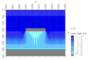
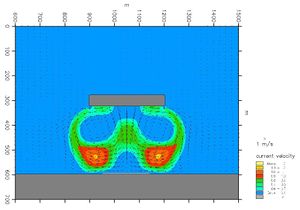
- The wave set-up on the foreshore is less in the sheltered area than outside, which generates local currents towards the sheltered area along the foreshore from both sides of the breakwater so that two eddies develop. These eddies also develop in the case of oblique wave approach.
- The longshore current is partially blocked by the circulation currents; this causes some of the longshore currents to be diverted outside the breakwater.
Wave and current conditions at a detached breakwater with a perpendicular wave approach.
And the following impact on the morphological conditions:
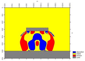
- The littoral transport in lee of the breakwater decreases due to the attenuated wave and longshore currents in the area sheltered by the breakwater. This causes the trapping of sand behind the breakwater depending on the conditions. As a rule-of- thumb, the trapping of sand will develop into a tombolo formation connecting the breakwater and the shore by sand deposits, if the length of the breakwater is equal to or longer than 0.8 times the distance between the shore and the breakwater. For shorter breakwaters, only a salient in the shoreline will develop.
- The diversion of the longshore currents will cause the development of local erosion close to the heads of the breakwater.
- The trapping of sand, especially if a tombolo has developed, will cause lee side erosion downstream of the breakwater. This downstream erosion is very similar to what is developed for groynes. However, there are more parameters involved in breakwaters, so it is possible to manipulate the transport in a more refined manner.
- A breakwater traps sand under all circumstances, even if the net transport is zero. This means also that there will be a coastal impact in any case.
Initial sediment transport pattern and initial morphological impact caused by a detached breakwater for perpendicular wave approach.
When several breakwaters are constructed in a row, the system is referred to as a segmented breakwater. A segmented breakwater is used to protect long sections of shoreline; the downstream coastal impact will be correspondingly larger than for a single breakwater.
Other impacts by breakwaters:
- If segmented breakwaters are constructed with too small gaps, the water exchange in the embayments between the breakwaters may be poor.
- Breakwaters normally obstruct part of the view over the sea, which means that the visual impact can be unacceptable.
- Swimmers may feel tempted to use the sheltered area in connection with detached breakwaters, but the circulation currents can be dangerous.
Passive Coastal Protection Structures
Other types of coastal protection that do not protrude into the sea will, however, also cause increased coastal erosion. Seawalls and revetments are typically constructed along coastal sections to provide protection of the coast.
An eroding shore/coast supplies material to the littoral transport budget if the erosion is allowed to continue. When the erosion is stopped at certain sections by the construction of seawalls or revetments, the supply of sand from this section of the shoreline to the sediment budget along the adjacent sections of shorelines will stop, whereby these adjacent shorelines will be exposed to increased erosion. The active trapping structures, such as groynes and breakwaters, will also act in this way in addition to their more direct coastal impact as discussed above.
The erosion of high cliffs often appears to be very drastic, which is why they have, in many cases, been the first to be protected in an area. However, before their protection they were the main suppliers of sediments to the littoral cell in question. Consequently, their protection leads to increased erosion at adjacent lower sections of the coastline. The result is that the erosion has been shifted to less resistant areas resulting in higher area losses per year.
Erosion of Crescent-Shaped Bays
In areas where the coastal landscape is formed by an interaction between rocky headlands and a littoral transport regime, the shoreline configuration will often be in the form of crescent-shaped or spiral-shaped bays, see figure below: The correlation between the shape of a crescent-shaped bay and the transport supply to the bay.. The form and stability of these bays mainly depend on two factors:
- The wave climate, which is considered stable
- The supply of sand to the bay from the upstream bay, QE, and from a possible river, QR
The overall transport mechanisms in a crescent-shaped or spiral-shaped bay can be characterised as follows. The supply of sand from the upstream bay QB will pass the headland and cross the bay via a bar. If, as shown in the figure below, a river also contributes QR to the littoral budget, this material will be transported downdrift into the bay, partly along the shoreline and partly onto the bar. These transport processes are fairly complicated and 2-dimentional in nature, but they result in the supply of QB + QR to the straight downdrift section of the crescent-shaped shoreline of the bay. The direction of this straight section is given by the wave climate and the actual sum QS1 = QB + QR according to the transport correlation between incident wave direction α1 and the transport QS1, which is also shown in the figure.
The correlation between the shape of a crescent-shaped bay and the transport supply to the bay.
The shape of the crescent-shaped bay is stable, apart from seasonal variations, as long as the supply of material to the bay QS1 = QB + QR is not changed. However, if the supply of material to the bay is reduced, typically by changes to the upstream bay or changes to the river, the overall shape of the bay will also change, as the direction of the straight section will adjust to the new sum Q2, where Q2 < Q1, leading to erosion in the entire bay, as sketched in the figure.
This means that changes in one bay will gradually penetrate into the downstream bays, so crescent-shaped bays, although they appear fairly stable, are actually very sensitive to changes in the supply of sand.
River Regulation Works and Sand Mining in Rivers
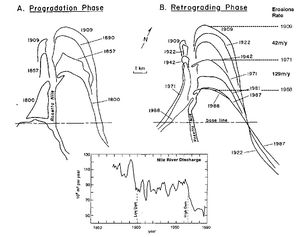
A decrease in the supply of sediments to a shoreline, due to the regulation of rivers, which previously supplied material to the shoreline, is a very common cause of coastal erosion. The river regulation works can be the construction of dams for power production and irrigation purposes, or the deepening of navigation channels and sand mining, but all of them cause less supply of sediment to the shoreline. Perhaps the best-known example of this is the trapping of the sediments of the Nile River by the construction of the High Aswan Dam in the 1960´s, see figure below: Natural delta accretion (left) and coastal erosion (right) of the Rosetta Promontory of the Nile delta caused mainly by the construction of the high Aswan Dam in the 1960´s.
Natural delta accretion (left) and coastal erosion (right) of the Rosetta Promontory of the Nile delta caused mainly by the construction of the high Aswan Dam in the 1960´s.
The promontory propagated until 1909 and then began to erode. The reasons for the erosion of 42 m/year during the period 1909-1971 were mainly a reduction in the river discharge and the construction of the Low Aswan Dam, whereas the drastically increased erosion rate of 129 m/year after 1971 was caused by the construction of the High Aswan Dam.
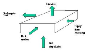
Sand mining in rivers is a major cause of coastal erosion in many countries, such as Sri Lanka. The supply of sand to the coast Qcoa from a river depends of many parameters and there is no simple correlation between sand mining and decrease in supply to the coast. However, in general there are five components in the sediment balance for a degrading river section, refer the illustration in figure below: Sediment Balance for a rive segment. The components are:
Sources
- Sand supply from the catchment, Qcat
- Degradation of the river bed, Qbed
- Bank erosion, Qban
Sinks
- Sand extraction (sand mining), Qmin
- Sand discharge to the coast, Qcoa
Sediment Balance for a rive segment
The following equation must be fulfilled for a given segment of the river:
:Qcat + Qbed + Qban = Qmin + Qcoa
Sand mining in a river lowers its bottom, causes bank erosion and reduces the supply of sand to the coast. Dependent of the circumstances sand mining in a river may cause a drastic or moderate drop in supply to the coast. Many rivers consist of a steep upper part, the mountain part, and a gently sloping lower part, where the river crosses the coastal plain. Sand mining in the two parts of the river has very different impacts on the supply of sand to the coast. River morphology modelling for Sri Lankan rivers has shown the following pattern [1]:
- Sand extraction in the upper part of the river causes a parallel translation (lowering) of the bed and of the water surface in the river, hence no changes in the sediment transport capacity. Thus the sand extraction in the upper part of the river is almost entirely balanced by local bed degradation, and has hardly any immediate impact on the supply of sand to the coast.
- Sand mining in the landward lower part of the river (far away from the mouth) will cause a local lowering of the river bed, but not a lowering of the water surface. This will cause a local decrease in the flow velocity and in the sediment transport capacity. This depression in the river bed will gradually be filled in from upstream supply, however dependent of the ratio between mining and catchment supply. The depression in the river bed will gradually travel towards the coast, however it may take many years before the impact, in the form of reduced sediment supply to the coast, is felt at the coast. But when the impact finally reaches the coast there may be an accumulated deficit in available river bed material corresponding to several decades sediment supply from the catchment. This means that an immediate halt in the sand mining will have hardly any remedial effect on the supply of sand to the coast, as the entire river bed has to be rebuild before the original supply is re-established. In the case of the Kelani River in Sri Lanka, it was calculated that it will take more than 70 years for the original river bed and the supply to the coast to recover following a complete stop in the sand mining
- Sand mining close to the river mouth will cause a local lowering of the river bed and an immediate decrease in the supply of sand to the coast. Halt of the sand mining in this situation will relative quickly cause recover of the supply of sand to the coast.
The impact on the supply of sand to the coast caused by sand mining in rivers has been discussed above. However there are other severe impacts along the river basin, which also have to be taken into consideration in order to find an overall sustainable solution. An integrated approach taking into account all the impacts has to be applied. This requires close collaboration between river authorities and coastal authorities. The main river related impacts are the following:
- Tide penetrates deeper into rivers and estuaries, which may cause increased saline intrusion in river estuaries, especially during the dry season, causing troubles for water intakes and for irrigation and causing changes to the estuarine habitats
- Increased flooding origination from the sea
- Lowering of the beds of the rivers also cause lowering of the water level in the rivers, which affects the ground water table in the flood plains. This may have impact on the agriculture especially during the dry period. This also causes problems for intakes to older irrigation schemes as they are now above the water level in the river
- Reduction of flood levels for small and medium sized floods as the deepened river bed and the low water level provides more volume between the river banks. However, the extreme floods will still spread over the flood plains. The absence of regular "small" inundations is likely to enhance man's encroachment on to the flood plain, thus causing increased "flooding problems" when the real large floods occur.
Wake from Fast Ferries
The special wake generated by fast ferries is characterised by a series of approximately 10 relatively low waves (Hs in the order of magnitude maximum 1 m), but relatively long waves. These wake waves are very similar to swell waves and they are exposed to considerable shoaling when approaching the coast. They often break as plunging breakers.
If a fast ferry navigates through protected waters, the wake waves are very different from the natural waves along the navigation route. The wake waves caused by fast ferries may influence the coastal conditions in the following ways:
- by higher wave uprush than that produced by normal waves
- by changing the coastal morphological processes in the area. This can result in erosion as well as the formation of a large beach berm
- by breaking unexpectedly and violently, the waves can be dangerous for small dinghies and for bathers
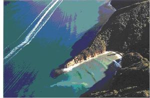
A precondition for approval of a new fast ferry route is therefore to perform an environmental impact assessment study. This will often result in navigation restrictions for certain parts of the route. An example of the impact of such waves is presented in figure below: Wake waves from a fast ferry in Tory Channel, Queen Charlotte Sound, New Zealand. Note the violent breaking, turbid water and rip currents., where breaking waves in a local bay caused by a passing fast ferry generate violent breaking and associated turbid water and rip currents in an otherwise relatively protected environment in Tory Channel, Queen Charlotte Sound, New Zealand.’
Wake waves from a fast ferry in Tory Channel, Queen Charlotte Sound, New Zealand. Note the violent breaking, turbid water and rip currents. (Copyright: Marlborough District Council, photographer: Graeme Matthews).
Sand and Coral Mining, and Maintenance Dredging
The mining of sand and gravel along beaches and in the surf-zone will cause erosion by depleting the shore of its sediment resources.
In connection with maintenance dredging of tidal inlets, harbours, and navigation channels, sand is very often lost from the littoral budget because the sand, unless otherwise regulated by legislation, is normally dumped at deep water. Suitable mitigating measures in terms of optimal layout of the port for the minimisation of sedimentation and bypassing techniques are discussed further in (LINK: Section 13.)
Coral mining and other means of spoiling the protective coral reefs, for example, fishing by the use of explosives or pollution, will also cause coastal erosion and beach degradation. The protective function of the reef disappears and the production of carbonate sand stops.
Concluding Remarks
In conclusion, it can be seen that nearly every type of development and coastal protection along a littoral shoreline or along rivers will result in erosion of the adjacent shores and coasts.
An overview over sediment sources and losses to the coastal zone is presented in figure below: Overview over sediment sources and losses to the coastal area.
Overview over sediment sources and losses to the coastal area
References
- ↑ Mangor, K., 2002. Shoreline Management, Background Document for the second revision of the Coastal Zone Management Plan, Sri Lanka, 2002. Performed under the Coastal Resources Management Program, Sri Lanka. ADB TA No. 3477 SRI
Author: Karsten Mangor, DHI, 2004. km@dhi.dk.


