Monitoring coastal morphodynamics using high-precision multibeam technology
Contents
Monitoring coastal morphodynamics using high-precision multibeam technology
Introduction
Coastal erosion, bathymetric changes of the near coast seabed or the stability and dispersal of dredged and disposed material are among the key questions of coastal management: What are the effects of coastal protection measures? How effective are they? Do they generate new burdens on the coastal system? Which processes control the movement of the seabed? What are the typical scales for the rearrangement of bed material? What types of seabed structures contribute most to the transport of the bed material? To what extent are morpho- logical changes predictable? Answers to these questions are still limited by a lack of observational evidence. Most of all, area-wide data are required to allow for comprehensive views of the relevant bed structures ranging over horizontal scales from decimeters to kilometers. The detection of seabed changes over these wide ranges of scales requires observational systems that combine high spatial resolution down to decimeters with high precision and accuracy in the horizontal and vertical positioning of the seabed structures in the range of centimeters.
Techniques and Methods
In the last decade multibeam echosounder systems became a widely used tool for seabed mapping and have replaced the traditional single beam surveys. Seabed mapping based on single beam transects relies substantially on spatial interpolation methods, often guided by manual expert interference. In contrast, multibeam systems provide dense observational two-dimensional net- works of depth soundings, from which a continuous digital terrain model of the seabed can be constructed.
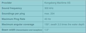
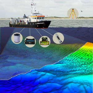
The high spatial resolution of the multibeam method is achieved by high frequency transmission of an echosounder swath that is received in highly directional re- solution by means of phase discrimination technique. The characteristic numbers of the system used by GKSS are listed in Table 1 and the system’s components depicted in Fig. 1. Beam arrival times are trans- formed into distances by sampled vertical sound profiles combined with modelling of ray propagation. Any ship movement is compensated for by rapidly sampling motion sensors. Dynamical vertical and horizontal positioning of the multibeam-transducer with cm-precision is achieved using real-time kinematic global positioning (GPS-RTK) and a high quality gyro compass.
Limitations and Problems
The multibeam system requires a water depth of at least 3 m, a value that is also needed for shipping safety. The quality of the observations depends strongly on the effective compensation of the ship motion and a high quality of the GPS signals. This constrains the range for high-quality mappings to distances of 10 to 20 km away from the land-based GPS- reference stations and survey periods to moderate wave conditions. Repeated sampling of stable immobile seabed structures (fishing drag-board traces, ship wrecks) indicates that the reconstructed overall vertical position with respect to a fixed chart datum may vary by more than 10 cm from survey to survey. The causes of this variation have not been resolved yet. Hence, with- out a vertical reference present within the surveyed area overall variations in the seabed of less than 20 cm cannot be derived unambiguously over periods longer than several months. In contrast, using a fixed seabed structure as vertical reference the precision of multibeam data can be less then half a meter in the horizon- tal and one centimeter in the vertical, as demonstrated at the German Baltic coast (Fig. 2).
Example: The fate of dumped material at the German Baltic Coast
Problem
Harbours, rivers and estuaries all over the world have to be dredged to remain navigable for modern sea traffic. Dredged material is often highly polluted and there is much concern about the dispersal of the material during and after dumping. For the German Baltic coast, this was studied in more detail close to Rostock-Warne- münde harbour (Fig. 3) within the framework of the DYNAS-project (Dynamics of natural and anthropogenic sedimentation, Harff et al., 2003, 2005). The fate of dredged material dumped into a site closed for shipping activity was followed over more than three years from June 2001 to August 2004 by means of multibeam tech- nology (Stockmann et al., in print).
Results
The settled disposals consisted mainly of glacial till and formed crater-like structures reflecting the transfer of downwards into radial momentum after impact (Fig. 4). The seabed structures of the disposals showed only little change over time and their quantification by the multibeam echosounder surveys required a high measuring precision in the order of a few cm in the vertical. Volume estimations of the bed disposals revealed that material was transported away only during the dumping phase. Over the following years only reworking of the material took place: the surface smoothed out (see Fig. 4) and this process was faster at smaller horizontal scales (see Fig. 5). From the rate of the observed bathymetric changes, the material properties and model based wave and bed shear stress statistics it was estimated that these structures as a whole would persist for about a century (see Table 2).
Management implications
The observations have some consequences for the dumping management. As long as glacial till is dumped at comparably sheltered sites the loss and further dispersal of the dredged material is negligible over decades. Dumped material consisting of silt and sand may be transported away to a substantial degree in the form of plumes and be widely dispersed due to low settling velocities. As silt is the material with the lowest settling velocities in dredged sediment mixtures and also the most polluted material, coastal zone management must focus on the handling of this fraction of the dredged material. At the same time, glacial till chunks have a limited use in covering highly polluted seabed. Although they possess a high stability when deposited on the bed it will be most demanding to achieve a sufficient area-wide coverage as the radial dispersion of the settled material is very limited and further spreading very slow.
References
Please note that others may also have edited the contents of this article.
|
Please note that others may also have edited the contents of this article.
|
Please note that others may also have edited the contents of this article.
|

