Use of Lidar for coastal habitat mapping
This article describes how Lidar (Laser or Light Detection and Ranging) can be used to collect data about coastal habitats. The article gives an introduction of the measurement principle and also explains how to plan for a Lidar-survey. More information about the conversion of collected data and the output of Lidar can be found in the article Data processing and output of Lidar.
Contents
Introduction
Lidar (Laser Induced Detection And Ranging or LIght Detection And Ranging) is an active remote sensing
technique using light emission. Part of the light is diffused or absorbed by the environment and the other part is backscattered in the direction of the source of radiation. The time difference between signal emission and signal reception makes it possible to determine the distance covered since the speed of light is known. Knowing the precise altitude of the aircraft, it is then possible to determine altimetry (or bathymetry) in each point having received the radiation. The remote sensing components of Lidar include:
- a Laser (Light Amplification by Stimulated Emission of Radiation) telemeter also called Laser Scanner,
- a telescope allowing the measurement of backscattered light intensity, and
- acquisition electronics and electro-optical components.
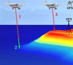
The absolute positioning of the laser scanner (see Figure 2) is ensured thanks to a GPS receiver (Global Positioning System) and an Inertial Navigation System (INS). The GPS System is used in differential kinematics, with one receiver aboard the plane and one or more others stationed at reference points on the ground. The role of the GPS in a GPS/INS integration of the plane's trajectory is to provide the XYZ position, the fastest systems having a frequency of 10Hz. The INS provides the plane altitude at a 100 Hz frequency. The combination of GPS and INS makes it possible to correct the respective defects of each system. Thus, the long-term drift of the inertial platform is corrected by the GPS system's stability.
Advantages of Lidar in the coastal zone
The main reason for using Lidar in the coastal zone is its capacity of rapidly covering large areas which are otherwise difficult to survey with more conventional tools. Thanks to the high sensing frequency the rate of coverage is very high, typically about 20 km² and over 50 km² per hour or more for hydrographic and topographic modes, respectively. For the tidal zone, this is crucial as usually only short tide windows are available for operations. No field system can achieve comparable coverage rates.
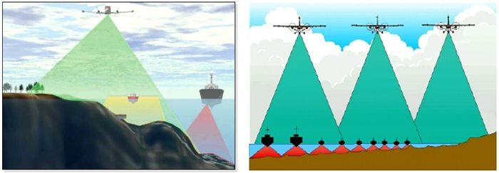
Hydrographic Lidar can be used to complement acoustic survey techniques in several ways. While acoustic multibeam systems have revolutionised bathymetric data acquisition in medium and deep waters, they are generally much less effective in shallow water (less than 20 m below LAT). In contrast, Lidar systems have been specifically designed for use in such challenging environments and can provide uniform and dense data in even the shallowest water.
Lidar primarily delivers three dimensional (x,y,z) ground coordinates also called a digital elevation model (DEM). With high density recordings, the presence of typical objects such as vegetation, buildings, underwater obstructions etc. can be inferred. It also delivers a signal intensity which under certain conditions could provide access to the reflectance of ground units.
Range of systems
Two main systems are available, topographic Lidar and hydrographic (also called bathymetric) Lidar. Today many instruments are dual function, i.e. running both modes simultaneously.
Topographic Lidar
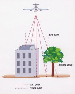
Topographic Lidar uses a near-infrared laser beam in the range of 1047 to 1540 nm. Some features of topographic Lidar are given in Populus et al. 2001[3]. At a typical operating altitude of 1000 m above the ground, about 50 km² per hour can be covered. The topographic Lidar pulse undergoes multiple reflections on some obstacles, referred to as first pulse or last pulse, a property that allows vegetation and other complex objects to be identified (Figure 3). Additional options include a 4k x 4k integrated metric frame digital camera for geo-referenced (x,y,z) colour or colour-IR images with sub-pixel accuracy.
Airborne Laser Hydrography
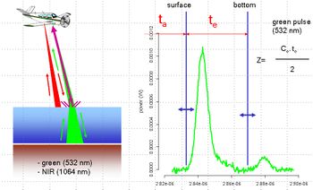
Airborne laser hydrography systems accurately determine water depths by measuring the time of flight of two laser pulses at different wavelengths: an infrared one is backscattered by the sea surface, the other one (typically green light at 532 nm) travels through the air-water interface to the bottom (Figure 4). An optical receiver on the aircraft detects the pulse reflections from both the seabed and the sea surface. The water depth is determined by the elapsed time between these two reflection/scattering events, after accounting for the system's operating geometry, propagation induced biases, wave height and tide effects.
The horizontal coordinates of the soundings are determined from the aircraft's position, altitude and attitude, the direction of the laser beam with respect to the aircraft and the measured water depth. The laser beams are swept in either an arc or a rectilinear scan across the direction of travel with a swath width typically half of the altitude. The surface sounding density can be varied from as little as 2 x 2 meters up to 5 x 5 m spacing and higher. Typical flying altitude is below 500 metres.
As light travels through the water column and reflects off the seafloor, scattering, absorption, and refraction all combine to limit the strength of the bottom return, and therefore the system's maximum extinction depth. This depth is a function of water clarity, and is generally about 3 times the Secchi depth (Smith et al., 2000[4]), but it also depends on bottom reflectance. Typical features of a topographic Lidar survey are given in table 1.The typical maximum depth capability is 40-50 m in very clear oligotrophic water. Heavy bottom vegetation and "fluid mud" may limit system performance as well. Lidar swath coverage is independent of the water depth. In general, Lidar systems will not be applicable in areas with chronic moderate to high turbidity. In areas where the turbidity may be variable over a wide range of values, it is critical to schedule Lidar operations during a period when the conditions are favourable, e.g. low discharge from coastal rivers and neap tide period.
Minimum depth capability is better than one metre and Lidar can now provide continuous topographic and bathymetric mapping through the shoreline from water onto land. Most systems also collect a directly downward-looking, geo-referenced video concurrently with the Lidar measurements. In addition to offering a visual record of the survey area, the video is frequently used to position coastal features such as navigation aids, piers, and other objects of interest.
Planning a survey
Planning a Lidar airborne survey requires taking many parameters into account (flight plan, tide, surface agitation, water turbidity, weather conditions, survey dot density, flight altitude, sun elevation, people present in survey area, etc.) in order to optimise work and guarantee good data quality.
Some general survey indications
Many of the operating tips are the same as for conventional airborne surveys. They are as follows:
- topographic Lidar can be used in daytime or at night, however hydrographic Lidar operators would rather work by day since they need simultaneous photographic coverage
- clouds are not really a problem, provided the aircraft remains below the cloud ceiling, however clear sky conditions are always preferable,
- the wind speed should be below 20 knots with a light sea state
- the sun elevation should not be more than 50° to avoid sun glint, as sun rays may create some noise in the return waveform. This is actually more critical with hydrographic Lidar for two reasons : a) the signal intensity is much lower due to water absorption, especially for deeper pings, b) most devices have a 20° incidence angle (front-looking conical incidence) which make them prone to sun glint. Flight lines should therefore run away from the sun.
- for tidal zone topography, sorties should be made from roughly 1.5 hour before to 1 hour after spring low tide; this allows the tidal area to be surveyed almost down to the LAT line. For hydrographic surveys, the neap low tide is ideal as it ensures reasonably low water levels combined with reduced currents and low sediment bottom scouring. Since the hydrographic survey rate of coverage is lower, sorties will be longer. In some cases, an entire half tide will be necessary, which will limit deeper bottom detection.
- September seems to be the best month in Western Europe in terms of turbidity, as river discharges and primary production are at their lowest at this time of the year.
- state of the art coverage rates on complex shores are roughly 50 and 15 km² per hour for topographic and hydrographic surveys respectively, however it should be noted that the dot density of the latter is typically 2-3 times lower than that of the former.
- as the use of dual Lidar during the same flight is increasingly common, a trade-off has to be found in terms of the survey tidal window. Neap low tide conditions will ensure the best overall work quality. In this case, the lower tidal zone which is underwater will be surveyed by the hydrographic Lidar, while the mid and upper tidal zone will be covered by the topographic sensor.
The choice of a particular Lidar system and its characteristics will also influence the ratio of cost, surface area covered and measurement density.
Example of a flight plan over the Mont Saint-Michel Bay, France (tidal)
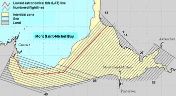
This particular job involved covering about 250 km² of tidal flats using topographic Lidar. The flight plan was rather straightforward to organise. Parallel flight lines with 20 % overlap were drawn in three boxes to optimise coverage, with respect to the shape of the bay. The longest possible flight lines were drawn, to reduce the number of U-turns with respect to the total flight time (a U-turn takes about 3-4 minutes at 150 knots). However, in the eastern estuary this rule could not be respected and shorter flight lines could not be avoided. The flight lines had to be positioned with respect to the varying water levels. The survey was therefore to start by covering mid-level lines 2 hours before low water and continued “going down with the tide” so that lines closest to LAT were flown when the tide was low. This allowed maximal coverage of the tidal zone.
Survey strategy in shallow water areas
To survey complex non-linear seashores, several options are available. To keep costs down, a single mobilisation of equipment is recommended. In this case, tidal conditions must be examined quite thoroughly with regard to the site’s oceanographic features (see "general survey indications")). The decision has then to be made whether to run two sorties or just one. A first sortie at higher altitude can be devoted to a topographic survey alone and be followed by a second sortie at lower altitude for the hydrographic survey. In such a case, both surveys are optimal and high quality data is obtained. If a dual system is used, flight time will be constrained by the lower frequency of the hydrographic system and its lower flight altitude, while the topographic Lidar data will be over-abundant. In situations where the proportion of shallow water to tidal flats is high (e.g. an archipelago), such a dual flight is clearly recommended. Note that topographic Lidar can best be flown by night while hydrographic Lidar requires the simultaneous recording of imagery.
Flight height, swath and dot density
Since a given system will have a fixed frequency, dot spacing is a function of flight altitude and speed. Since accuracy decreases with altitude (due to atmospheric content) the flight parameters will be dictated by the project requirements in terms of both accuracy and dot spacing. Typical operating specifications permit flying speeds of 75 to 250 kilometres per hour, flying at heights of not less than 200 metres. Dot density depends on the instrument frequency and flight altitude. Recent topographic Lidars scan at frequencies close to 100,000 Hz, which currently provides a very high dot density (one dot per m²). Hydrographic Lidars, with a frequency of around 4,000 Hz can achieve a dot density of about one per 10 to 4 m² at most by fine-tuning the aircraft altitude and speed. Lidar systems feature a beam incidence between 15° and 20°, which creates a swath width of 0.5 to 0.7 times the altitude. While topographic Lidar systems scan either side of the nadir position (hence a changing looking incidence for each dot), hydrographic Lidar is designed with a conical front-looking angle which ensures a constant beam incidence. This is due to the need for a similar refraction angle at the air-sea interface for all beams. Very small beam divergence on topographic Lidar results in a footprint of a few decimetres on the ground and hence a very accurate measurement. This cannot be achieved with hydrographic Lidar for technical reasons and the footprint is typically 2 to 3 metres on the surface. Since light travels through water, the footprint does not change. As the backscattered light comes from a rather large surface (approximately 10 m²), accuracy cannot be maintained at very high levels and typically reaches 0.25 m on sediment bottoms.
See also
Internal links
- Data processing and output of Lidar
- Definition of remote sensing
- Satellite-derived shoreline and nearshore bathymetry
References
- ↑ Banic J., Cunningham G., 1998. Airborne Laser Bathymetry: A tool for the Next Millennium. Optech Inc. (Toronto, Ontario, Canada,), pp. 6.
- ↑ Guenther G. C., Cunningham G., Laroque P. E., Reid D. J., 2000. Meeting the accuracy challenge in Airborne Lidar bathymetry, Proceedings of EARSeL-SIG-Workshop Lidar, Dresden/FRG, June 16 – 17, 2000, pp. 27.
- ↑ Populus et al., 2001. Assessment of the Lidar topographic technique over a coastal area. CoastGIS’01, Second International Symposium on GIS and Computer Mapping for Coastal Zone Management, Halifax, June 18-20, 2001.
- ↑ Smith R.A., Irish J.L., Smith M.Q., 2000. Airborne Lidar and airborne hyperspectral imagery: a fusion of two proven sensors for improved hydrographic surveying, Proceedings of Canadian Hydrographic Conference 2000, Montreal (Canada), pp. 10
Please note that others may also have edited the contents of this article.
|
